Wiring
STM32F405 Feather Express
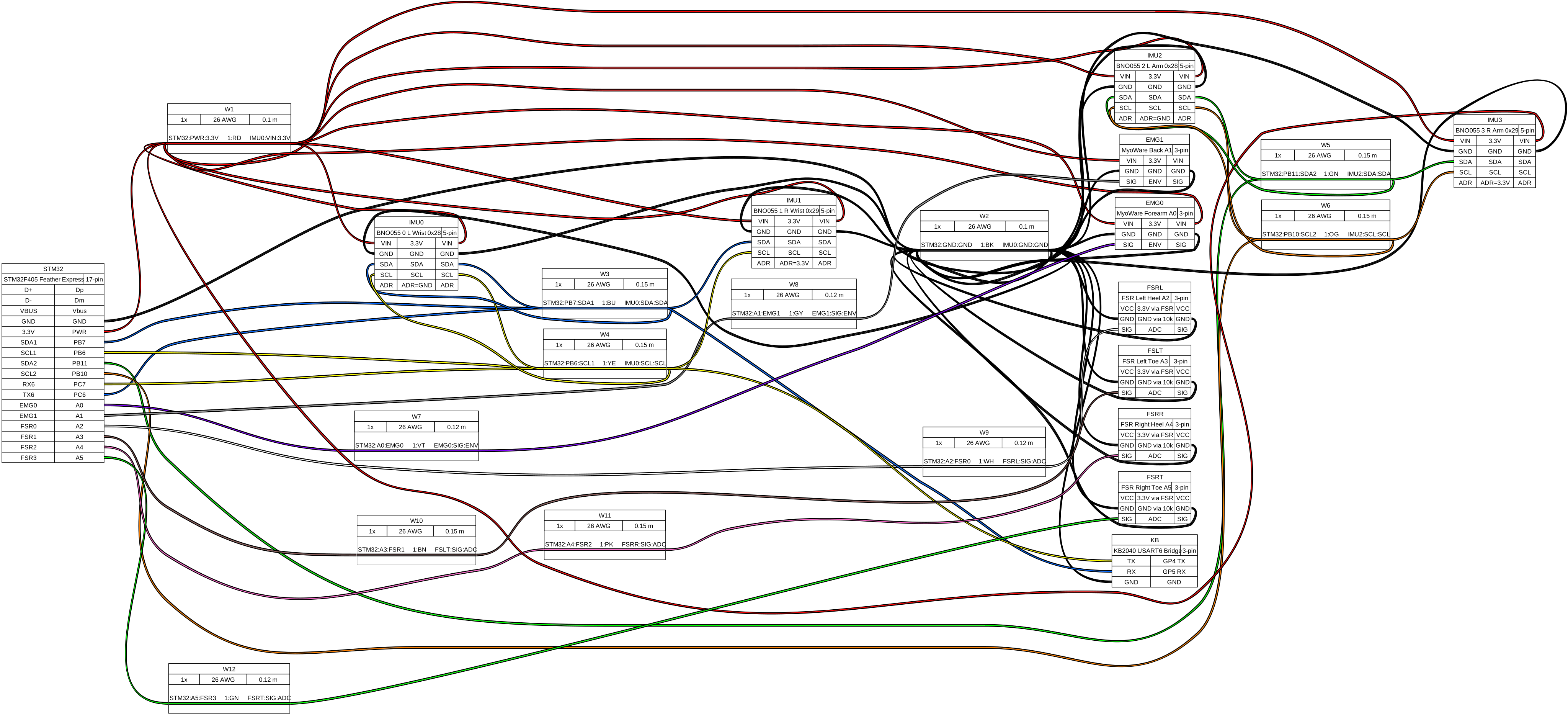
The STM32F405 is the primary MCU. It reads 4 BNO055 IMUs (I2C1 + I2C2), 6 ADC channels (2 MyoWare + 4 FSR), receives the KB2040 relay frame over USART6, and streams the unified 214-byte packet over USB CDC to the PC.
I2C buses
| Bus | Port pins | Silkscreen | Devices |
|---|---|---|---|
| I2C1 | PB7 (SDA), PB6 (SCL) | SDA / SCL pads | BNO055 #0 L wrist (0x28), BNO055 #1 R wrist (0x29) |
| I2C2 | PB11 (SDA), PB10 (SCL) | D0 / D1 | BNO055 #2 L arm (0x28), BNO055 #3 R arm (0x29) |
Each bus supports two addresses (0x28 and 0x29), selected by the ADR pin on the BNO055: - ADR = GND → 0x28 - ADR = 3.3 V → 0x29
Pull-up resistors
BNO055 can stretch the I²C clock up to ~700 µs during fusion. Use 4.7 kΩ pull-ups on SDA/SCL. The STM32 hardware I²C handles clock stretching; if reads fail intermittently, check the pull-ups first.
ADC channels
| Pin | Sensor | Signal |
|---|---|---|
| A0 | MyoWare forearm flexor | 0–3.3 V (envelope) |
| A1 | MyoWare lumbar erector | 0–3.3 V (envelope) |
| A2 | FSR left heel | voltage divider, 0–3.3 V |
| A3 | FSR left toe | voltage divider, 0–3.3 V |
| A4 | FSR right heel | voltage divider, 0–3.3 V |
| A5 | FSR right toe | voltage divider, 0–3.3 V |
FSR voltage divider: 10 kΩ pull-down per sensor. Connect one FSR leg to 3.3 V, the other leg to ADC pin + 10 kΩ to GND.
USART6 (KB2040 bridge)
| STM32 pin | Direction | KB2040 pin |
|---|---|---|
| PC6 (TX) | → | GP5 (RX) |
| PC7 (RX) | ← | GP4 (TX) |
921600 baud, 8N1. The KB2040 sends a 70-byte frame every 10 ms.
KB2040
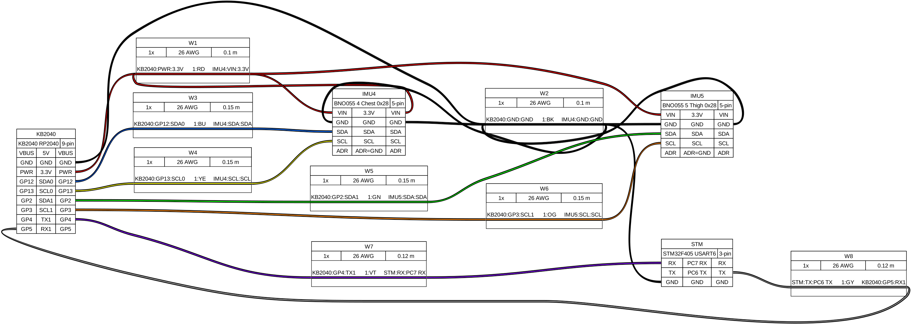
The KB2040 is the I²C co-processor. It reads 2 BNO055 IMUs (chest, thigh) and sends the 70-byte frame to the STM32 over Serial1 (UART1).
I2C buses
| Bus | Port pins | Silkscreen | Devices |
|---|---|---|---|
| I2C0 | GP12 (SDA), GP13 (SCL) | D12 / D13 | BNO055 #4 chest (0x28) |
| I2C1 | GP2 (SDA), GP3 (SCL) | D2 / D3 | BNO055 #5 thigh (0x28) |
Both IMUs at address 0x28 (ADR = GND) since they are on separate buses.
Serial1 (UART to STM32)
| KB2040 pin | Direction | STM32 pin |
|---|---|---|
| GP4 (TX) | → | PC7 (RX) |
| GP5 (RX) | ← | PC6 (TX) |
Power
Both MCUs power up via USB-C. The STM32 USB-C also carries data (CDC serial). The KB2040 USB-C is for power only if connected directly to a battery; it can also be powered via the STM32's 3.3 V rail through the UART connection (GND + VIN).
All BNO055 sensors are powered from the 3.3 V rail on their respective MCU. MyoWare sensors need 3.3–5 V (STM32 3.3 V is sufficient). FSR voltage dividers use the 3.3 V rail.
Quick connectivity check
After flashing both MCUs (see Flashing):
- Connect STM32 USB-C to PC
- Open serial monitor at 115200 baud —
pio device monitor -b 115200fromfirmware/stm32f405/ - Verify:
[IMU] 0:ok 1:ok 2:ok 3:ok(initialization logs) - Run:
.venv/bin/python -m host.serial_reader - Verify: frames with
seq=Nand valid CRC appear at ~100 Hz